In this guide, we explore the Raspberry Pi 4 GPIO Pinout, a crucial aspect of harnessing the full power of this single-board computer. A compact single-board computer that brings desktop-level performance to the world of DIY electronics, IoT, media centers, and industrial automation. Whether you’re building a retro gaming console or a Kubernetes cluster, the Pi 4 Model B offers unmatched versatility at an unbeatable price. In this guide, we’ll dive deep into the Raspberry Pi 4’s GPIO pinout, helping you harness its full potential with clarity and precision.
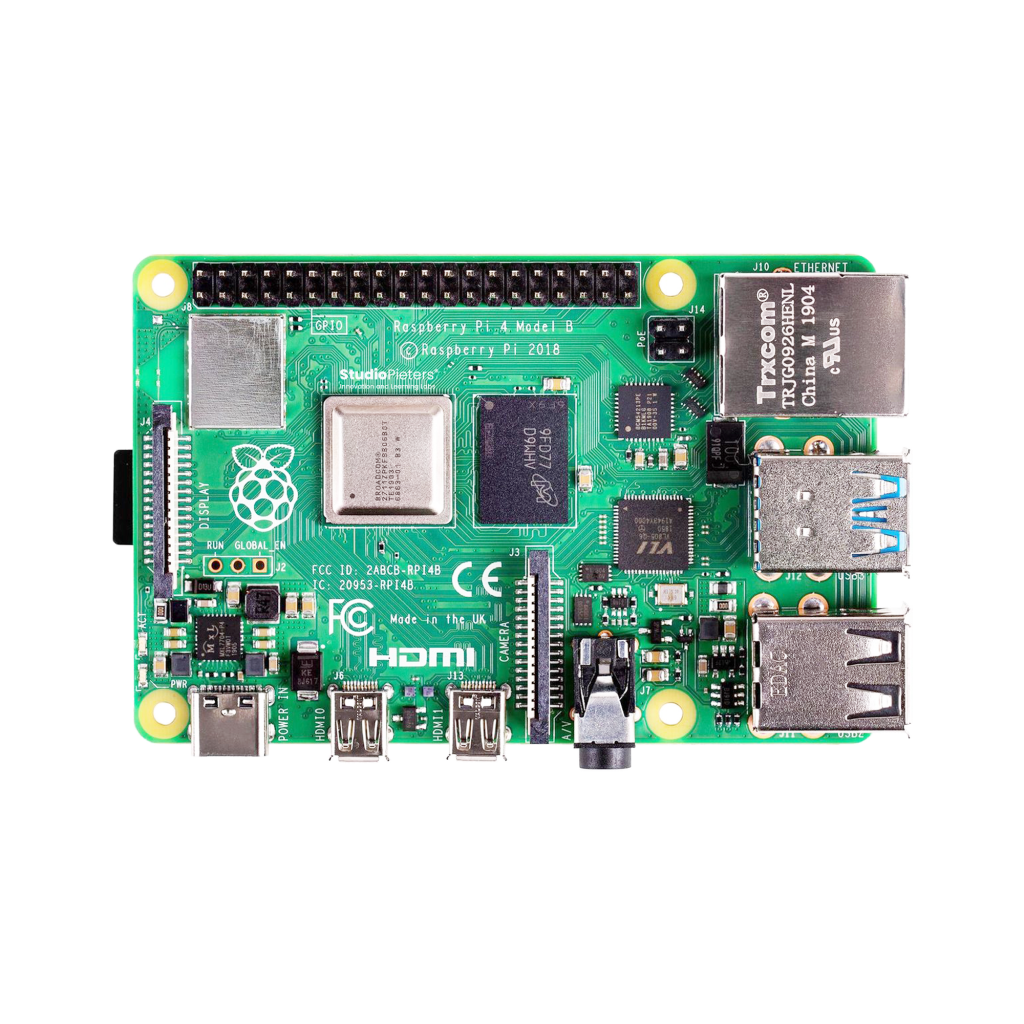
What is the Raspberry Pi 4 Model B?
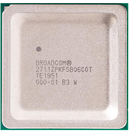
System-on-Module (SoM):
At its core, the Raspberry Pi 4 Model B features a Broadcom BCM2711 SoC with a quad-core Cortex-A72 64-bit processor clocked at 1.5 GHz. It comes in three memory configurations (2 GB, 4 GB, and 8 GB LPDDR4 RAM), making it suitable for both lightweight and memory-intensive applications.
Connectivity:
The Pi 4 dramatically improves upon its predecessors with enhanced I/O: dual-band 802.11ac Wi-Fi, Bluetooth 5.0, true Gigabit Ethernet, two USB 3.0 ports, two USB 2.0 ports, and dual micro-HDMI outputs (supporting up to 4Kp60). A new USB-C connector supplies stable 5V/3A power.
GPIO Header:
A 40-pin header exposes 26 GPIO’s, multiple power pins, and essential interfaces like I2C, SPI, UART, and PWM. This interface makes the Pi 4 ideal for real-world hardware integration.
Designed for Connectivity, Control, and Computation
The Raspberry Pi 4 Model B supports a wide array of features through its 40-pin GPIO header:
- 26 general-purpose I/O pins
- 3.3V logic level (do not connect 5V directly to GPIOs!)
- SPI, I2C, UART, PWM
- 3.3V and 5V power outputs
- Multiple ground (GND) connections
- Support for HAT EEPROM auto-detection
- ID_SD and ID_SC pins for hardware identification
With this level of flexibility, the Raspberry Pi 4 can connect to virtually any sensor, actuator, or peripheral device.

** The Raspberry Pi 4 pinout is available for download at the end of this post in high resolution – for free!
GPIO Power Pins
The GPIO header includes multiple power supply lines. Pins 1 and 17 provide 3.3V, while pins 2 and 4 offer a direct 5V output from the USB-C power source. Ground pins are available at positions 6, 9, 14, 20, 25, 30, 34, and 39. These power rails enable direct powering of sensors, displays, and low-power actuators.

General Purpose Input/Output
There are 26 GPIO’s available on the Pi 4. Each GPIO is 3.3V logic and capable of both input and output. Input pins are used for reading sensors or button states, while output pins control LED’s, relays, and other devices. Be aware that GPIO’s are limited to a maximum current draw of ~16 mA per pin and ~50 mA total across all pins.

I2C – Inter-Integrated Circuit
The I2C bus allows multiple devices to communicate using only two wires: SDA (data) and SCL (clock). The default I2C1 interface is exposed on GPIO2 (SDA) and GPIO3 (SCL), located at pins 3 and 5 respectively. You’ll often find I2C used for connecting temperature sensors, OLED displays, and real-time clocks.
Note: pull-up resistors are required on the bus lines.

SPI – Serial Peripheral Interface
SPI enables fast communication with peripherals using four primary signals: MOSI (Master Out Slave In), MISO (Master In Slave Out), SCLK (clock), and CS (chip select). The Raspberry Pi exposes SPI0 by default with MOSI on GPIO10 (pin 19), MISO on GPIO9 (pin 21), SCLK on GPIO11 (pin 23), and CS lines on GPIO8 (CE0, pin 24) and GPIO7 (CE1, pin 26). Ideal for displays, flash memory, and high-speed ADC’s.

UART – Serial Communication
The Pi’s default UART interface is available on GPIO14 (TX, pin 8) and GPIO15 (RX, pin 10). It supports communication with serial devices like GPS modules, Bluetooth interfaces, and console debugging tools. By default, this UART is used by the Linux terminal; to use it in your project, disable the console through raspi-config.

PWM – Pulse Width Modulation
To get the most out of your Raspberry Pi 4 GPIO Pinout, it’s important to understand which pins support hardware features like PWM, SPI, and I2C. PWM enables fine control of power to devices like LED’s or servo’s by modulating the duty cycle of a digital signal. Hardware PWM is available on GPIO12 (pin 32), GPIO13 (pin 33), GPIO18 (pin 12), and GPIO19 (pin 35). Additional software PWM can be implemented on most other GPIO’s using libraries such as RPi.GPIO or pigpio.

EEPROM ID Pins
GPIO0 and GPIO1, found at pins 27 and 28, are reserved for EEPROM identification of HATs (Hardware Attached on Top). These pins use I2C to detect the attached board and should not be used for general-purpose I/O unless you’re designing a custom HAT and know what you’re doing.

Raspberry Pi 4 GPIO pinout overview
| Pin | BCM | Name | Function(s) | Notes |
|---|---|---|---|---|
| 1 | — | 3.3V | Power | Constant 3.3V output |
| 2 | — | 5V | Power | Direct 5V from USB-C |
| 3 | 2 | SDA1 | I2C | Requires pull-up resistor |
| 4 | — | 5V | Power | Direct 5V from USB-C |
| 5 | 3 | SCL1 | I2C | Requires pull-up resistor |
| 6 | — | GND | Ground | — |
| 7 | 4 | GPIO4 | GPIO | General-purpose I/O |
| 8 | 14 | TXD0 | UART TX | Serial transmit |
| 9 | — | GND | Ground | — |
| 10 | 15 | RXD0 | UART RX | Serial receive |
| 11 | 17 | GPIO17 | GPIO | — |
| 12 | 18 | GPIO18 | GPIO, PWM | Hardware PWM |
| 13 | 27 | GPIO27 | GPIO | — |
| 14 | — | GND | Ground | — |
| 15 | 22 | GPIO22 | GPIO | — |
| 16 | 23 | GPIO23 | GPIO | — |
| 17 | — | 3.3V | Power | Constant 3.3V output |
| 18 | 24 | GPIO24 | GPIO | — |
| 19 | 10 | MOSI | SPI | SPI Master Out |
| 20 | — | GND | Ground | — |
| 21 | 9 | MISO | SPI | SPI Master In |
| 22 | 25 | GPIO25 | GPIO | — |
| 23 | 11 | SCLK | SPI | SPI Clock |
| 24 | 8 | CE0 | SPI Chip Select 0 | — |
| 25 | — | GND | Ground | — |
| 26 | 7 | CE1 | SPI Chip Select 1 | — |
| 27 | 0 | ID_SD | EEPROM I2C Data | Reserved for HATs |
| 28 | 1 | ID_SC | EEPROM I2C Clock | Reserved for HATs |
| 29 | 5 | GPIO5 | GPIO | — |
| 30 | — | GND | Ground | — |
| 31 | 6 | GPIO6 | GPIO | — |
| 32 | 12 | GPIO12 | GPIO, PWM | Hardware PWM |
| 33 | 13 | GPIO13 | GPIO, PWM | Hardware PWM |
| 34 | — | GND | Ground | — |
| 35 | 19 | GPIO19 | GPIO, PWM, SPI | Hardware PWM |
| 36 | 16 | GPIO16 | GPIO | — |
| 37 | 26 | GPIO26 | GPIO | — |
| 38 | 20 | GPIO20 | GPIO | — |
| 39 | — | GND | Ground | — |
| 40 | 21 | GPIO21 | GPIO | — |
Best Practices and Common Mistakes
Optimize your Raspberry Pi projects by avoiding these common mistakes:
- Do not apply more than 3.3V to any GPIO pin.
- Use level shifters when interfacing with 5V logic.
- Always use resistors for current protection when driving LED’s.
- Avoid using pins 27 and 28 unless designing a HAT.
- Clean up GPIO states at the end of your Python scripts.
- Avoid pulling too much current from 3.3V/5V rails.
- Debounce mechanical buttons in software or hardware.
How to Program the GPIO
Development Environments:
- Python (with
RPi.GPIO,gpiozero, orpigpio) - C/C++ with
wiringPiorlibgpiod - Node.js with
onofforpigpio
Basic Python Example (Blink an LED on GPIO17):
from gpiozero import LED
from time import sleep

led = LED(17)

while True:
    led.on()
    sleep(1)
    led.off()
    sleep(1)
Run the script with:
python3 blink.pyBe sure to enable GPIO access and run scripts with appropriate permissions (sudo if needed).
Conclusion: Engineered for Innovation
The Raspberry Pi 4 Model B is more than a computer – it’s a launchpad for creativity. With its powerful CPU, flexible GPIO’s, and vast ecosystem, it brings the future of embedded computing to your desktop. Mastering its GPIO layout empowers you to create smart projects that are limited only by your imagination.
Download the ESP32 pinout here in high resolution – for free*!
* Free to use under the MIT license — attribution is required.