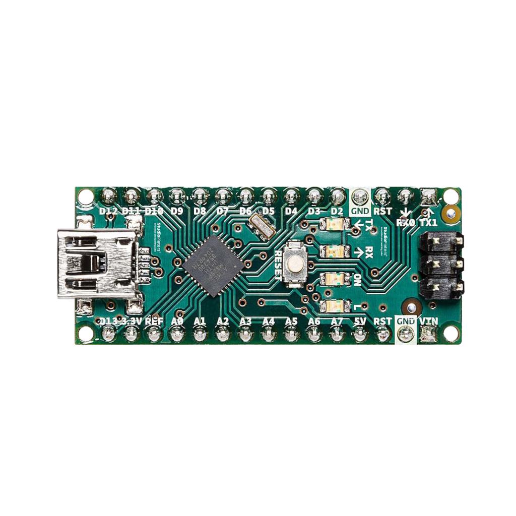
The Arduino® Nano is a compact yet powerful development board based on the ATmega328P microcontroller. Designed for small-scale projects and breadboard use, it offers all the core features of the Arduino® UNO in a much smaller footprint. Whether you’re building a sensor network, a wearable project, or automating something around the house, the Nano gives you everything you need — with flexibility and precision. In this guide, we’ll walk through the complete Arduino® Nano pinout — clearly and accurately — so you can start your project with confidence.
What is the Arduino® Nano?
Microcontroller:
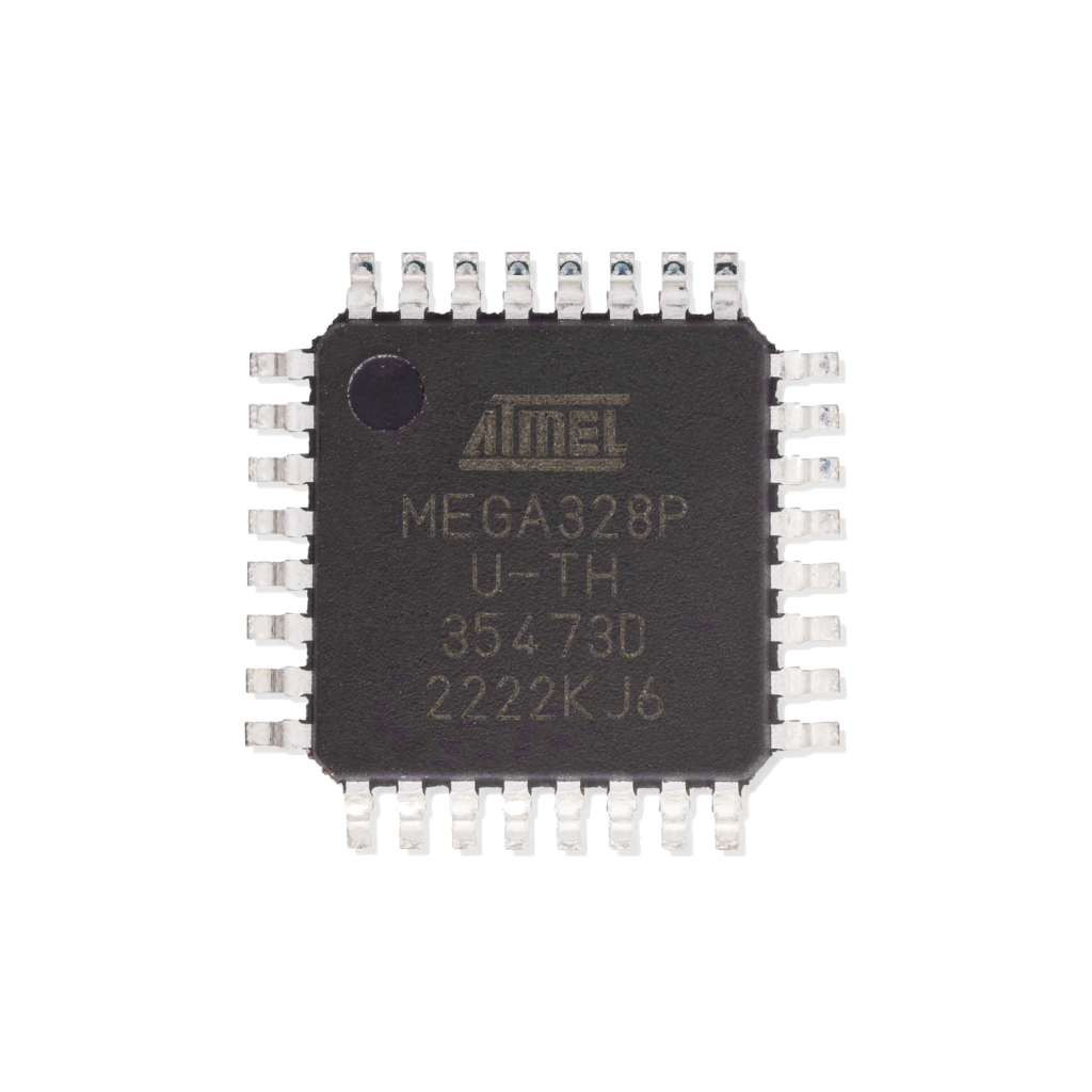
The heart of the Arduino® Nano is the ATmega328P, an 8-bit AVR microcontroller by Atmel (now part of Microchip). It runs at 16 MHz, with 32KB of flash memory, 2KB of SRAM, and 1KB of EEPROM.
Board Format:
The Nano’s design is breadboard-friendly and includes a mini-USB port for programming, ICSP header, onboard voltage regulation, and 30 easily accessible pins.
Power Supply Options
You can power the Arduino® Nano in two primary ways:
- VIN Pin: Accepts 7V–12V (recommended). It passes through the onboard voltage regulator. Supplying more than 12V may overheat the regulator; less than 7V might be insufficient.
- USB (Mini-B): Supplies a regulated 5V directly to the board from your computer or power bank. Max current: 500mA (shared between board and peripherals).
Regulated Outputs:
- 5V Pin: Outputs 5V from the onboard regulator or USB.
- 3.3V Pin: Supplies 3.3V (max ~50mA), derived from the onboard regulator.
- GND Pins (x2): Connect to ground. Essential for completing circuits and ensuring a common voltage reference.
RESET:
- One reset button and two RESET pins (all connected). Pulling RESET low restarts the microcontroller.

** The Arduino Nano pinout is available for download at the end of this post in high resolution – for free!
Analog Input Pins
The Arduino® Nano provides 8 analog input pins (A0–A7).
- ADC Resolution: 10-bit (0–1023)
- Voltage Range: 0–5V (relative to AREF or Vcc)
- Pins A6 and A7: Input only — not available as digital I/O
These pins use the onboard Analog-to-Digital Converter (ADC) to read voltages and convert them to digital values. Perfect for sensors, potentiometers, and analog monitoring.

Digital I/O Pins
There are 14 digital I/O pins on the Nano (D0–D13).
- Each pin can act as input or output.
- All pins support digital HIGH (5V) and LOW (0V) logic.
- Pin 13 is connected to the onboard LED.
- Current Limits:
- Max per pin: 40mA (absolute max; recommended: 20mA)
- Max total draw from all I/O: ~200mA

PWM (Pulse Width Modulation)
6 digital pins support PWM output:
- PWM Pins: D3, D5, D6, D9, D10, D11
- PWM Frequency: ~490Hz (default)
- Duty Cycle: Configurable via
analogWrite()(0–255)
Applications: Dim LEDs, control motor speed, generate audio signals.

Serial Communication
The Nano supports serial data exchange through:
- Hardware Serial (UART):
- RX (D0), TX (D1)
- Used for USB programming and serial monitor
- Software Serial: Additional serial ports can be simulated using the
SoftwareSeriallibrary (on any digital pins).
Note: Pins D0 and D1 are shared with USB communication. Avoid using them in regular sketches unless you handle serial carefully.

SPI Communication
The Nano includes an SPI interface for fast communication with peripherals:
- SPI Pins (on I/O headers):
- SS: D10
- MOSI: D11
- MISO: D12
- SCK: D13
- ICSP Header: Alternate SPI access, used for programming.
Applications: Connect to SD cards, shift registers, displays, etc.

I2C Communication
I2C enables communication with multiple devices using only two pins:
- SDA (Data): A4
- SCL (Clock): A5
Supports up to 255 devices on the same bus using unique addresses. Often used with sensors, real-time clocks, and displays.

External Interrupts
The Nano has two external interrupt pins:
- INT0: D2
- INT1: D3
These can trigger an interrupt on a signal change (RISING, FALLING, or CHANGE). Useful for rotary encoders, wake-on-event, or real-time triggers.
Pin Change Interrupts: Available on most other I/O pins via advanced programming.

Arduino® Nano GPIO Quick Reference Table
| Pin | Digital I/O | PWM | Analog In | Interrupt | Special Function |
|---|---|---|---|---|---|
| D0 | Yes (RX) | No | No | No | UART RX (Hardware Serial) |
| D1 | Yes (TX) | No | No | No | UART TX (Hardware Serial) |
| D2 | Yes | No | No | INT0 | External Interrupt 0 |
| D3 | Yes | Yes | No | INT1 | PWM Output, Interrupt |
| D4 | Yes | No | No | No | – |
| D5 | Yes | Yes | No | No | PWM Output |
| D6 | Yes | Yes | No | No | PWM Output |
| D7 | Yes | No | No | No | – |
| D8 | Yes | No | No | No | – |
| D9 | Yes | Yes | No | No | PWM Output |
| D10 | Yes | Yes | No | No | SPI SS (Slave Select) |
| D11 | Yes | Yes | No | No | SPI MOSI |
| D12 | Yes | No | No | No | SPI MISO |
| D13 | Yes | No | No | No | SPI SCK, Onboard LED |
| A0 | Yes | No | Yes | PCINT14 | Analog Input 0 |
| A1 | Yes | No | Yes | PCINT15 | Analog Input 1 |
| A2 | Yes | No | Yes | PCINT16 | Analog Input 2 |
| A3 | Yes | No | Yes | PCINT17 | Analog Input 3 |
| A4 | Yes | No | Yes | PCINT18 | I2C SDA |
| A5 | Yes | No | Yes | PCINT19 | I2C SCL |
| A6 | No | No | Yes | No | Analog-only |
| A7 | No | No | Yes | No | Analog-only |
AREF – Analog Reference
The AREF pin is used to set an external voltage reference for the ADC. Useful when using sensors with output ranges below 5V for increased accuracy.

ICSP Header
ICSP (In-Circuit Serial Programming) allows firmware flashing directly to the ATmega328P chip.
- Pins: 6-pin header
- Functions: MISO, MOSI, SCK, RESET, VCC, GND
- Used by bootloaders and ISP programmers (e.g. USBasp, USBtinyISP).

Best Practices and Common Mistakes
Optimize your Arduino® Nano projects by avoiding these common pitfalls:
- Don’t exceed 20mA per pin (even though 40mA is the absolute max).
- Avoid using pins D0 (RX) and D1 (TX) unless you’re not using serial communication via USB.
- Pins A6 and A7 are analog-only — don’t try to use them as digital I/O.
- Always connect all GNDs in your circuit for a common reference.
- Use decoupling capacitors (0.1µF) near sensors or modules to stabilize power.
- Match voltage levels when interfacing with 3.3V devices — use logic level shifters if needed.
- Don’t forget to debounce mechanical switches or use the
Bounce2library.
How to Program the Arduino® Nano
Development Environments:
You can write and upload code to the Arduino® Nano using:
- Arduino IDE – Simple, widely supported, perfect for beginners and quick testing.
- PlatformIO – Advanced development platform with auto-completion, debugging, and Git integration.
- AVR-GCC / Atmel Studio – For low-level AVR development and professional control.
Programming Interface:
| Function | Pin | Description |
|---|---|---|
| TX | D1 | Transmit serial data to PC (via USB) |
| RX | D0 | Receive serial data from PC |
| RESET | RESET pin or button | Resets the microcontroller |
| ICSP | 6-pin header | Used to burn the bootloader or reflash firmware |
Steps to Upload Code:
- Connect the Nano via mini-USB.
- In the Arduino IDE, select Board: “Arduino Nano”.
- Select the correct Processor (usually ATmega328P or ATmega328P (Old Bootloader)).
- Choose the right COM port.
- Click Upload.
Conclusion: Compact Power, Infinite Possibilities
The Arduino® Nano may be small, but it’s built for serious development. From controlling LED’s and sensors to managing motors and displays, it has everything you need to build compact, powerful electronics. Understanding the Nano’s pinout unlocks your creativity and gives you full control over your project’s potential.
Happy building!
Download the Arduino® Nano Pinout in High Resolution
Download the Arduino® Nano pinout here in high resolution – for free*!
* Free to use under the MIT license — attribution is required.