The ESP32 is one of the most versatile microcontrollers available today. Designed for performance and flexibility, it powers everything from smart home devices to advanced IoT systems. Whether you’re a hobbyist or a professional engineer, the ESP32 offers everything you need to bring your ideas to life — seamlessly and efficiently. In this guide, you’ll learn everything about the ESP32 pinout, with the clear and structured style you expect from the world’s leading technology manuals.
What is the ESP32?
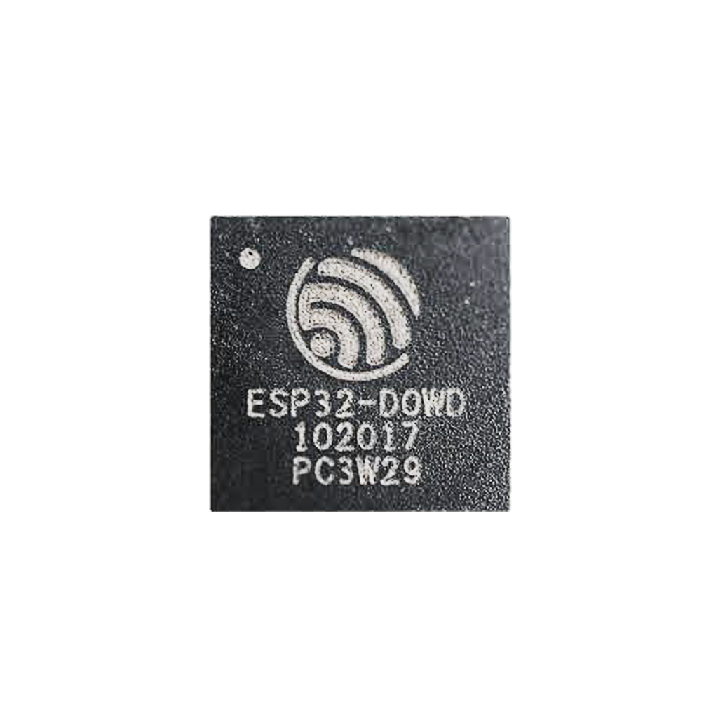
System-on-Chip (SoC): At the heart of the ESP32 lies a powerful SoC, developed by Espressif Systems. With dual-core Tensilica Xtensa LX6 processors, integrated Wi-Fi and Bluetooth, and a comprehensive suite of peripherals, the ESP32 is engineered for wireless, smart applications that require high performance and low power consumption.
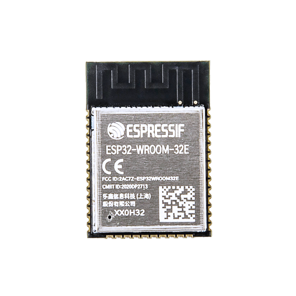
Module: The ESP-WROOM-32 module integrates the ESP32 chip, a crystal oscillator, flash memory, and passive components in a compact form factor, simplifying integration into a wide range of designs.
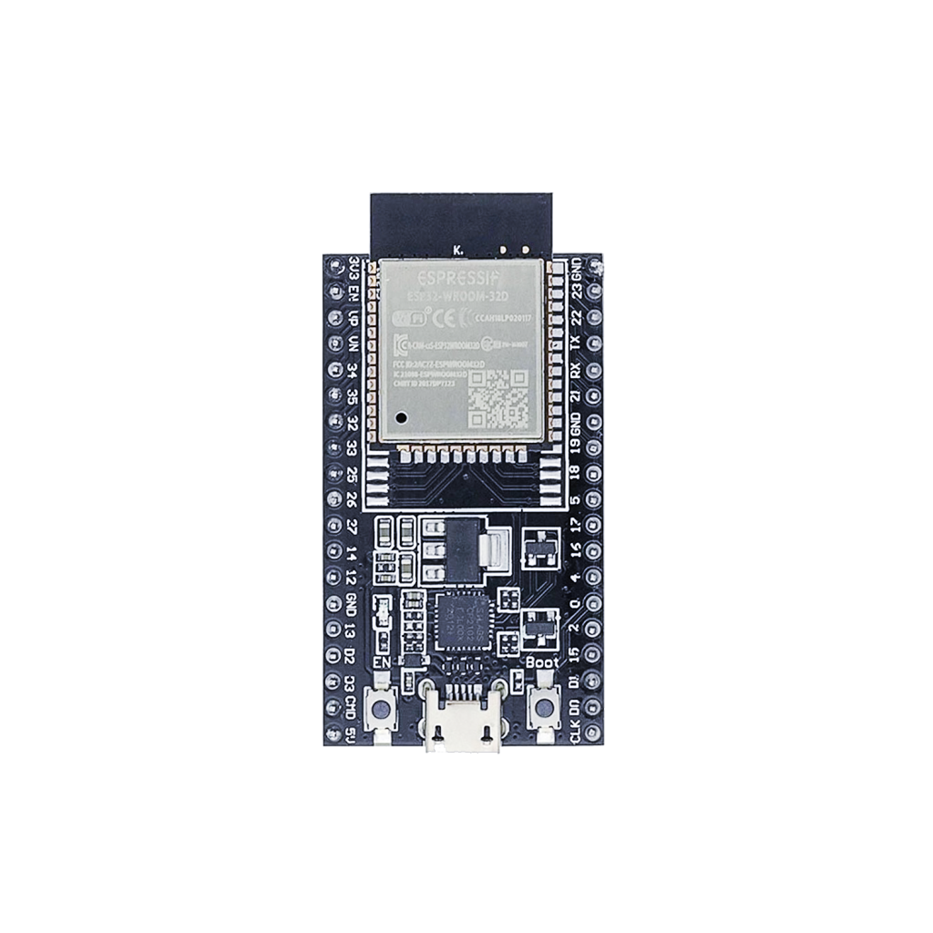
Development Board (DevKit): The ESP32 DevKit, like the popular DevKitC, presents the module on a development board with USB interface, voltage regulation, and accessible GPIOs, making it ideal for prototyping and rapid development.
Designed for Connectivity and Control
The ESP32 supports a wide array of peripherals and features that make it uniquely adaptable to virtually any application:
- Wi-Fi (802.11 b/g/n)
- Bluetooth v4.2 BR/EDR and BLE
- 34 programmable GPIOs
- 12-bit ADCs
- 2x 8-bit DACs
- Capacitive touch sensors
- SPI, I2C, UART, CAN, PWM, I2S
- Hall-effect sensor
- Secure encryption and cryptographic acceleration
With this range of capabilities, the ESP32 delivers seamless integration into smart homes, industrial environments, and portable devices.

** The ESP32 pinout is available for download at the end of this post in high resolution – for free!
ESP32 pinout – GPIO Fundamentals
The ESP32 provides extensive GPIO options. However, not all pins are identical. Some are designed exclusively for input, while others are optimized for special functions.
Input-Only Pins
GPIO34, GPIO35, GPIO36 (VP), GPIO39 (VN)
These pins are dedicated to input functions. They are perfect for reading sensors but cannot output signals.

SPI Flash Connected Pins
Pins GPIO6 to GPIO11 are internally connected to the SPI flash memory and should not be repurposed for other applications. Proper use ensures stability and optimal performance.

Advanced GPIO Features
Capacitive Touch GPIO’s
The ESP32 includes ten internal capacitive touch sensors, which measure variations in electrical charge. These can detect a human touch without mechanical movement.
- Applications: Replace mechanical buttons, create touch-sensitive controls, or use touch events to wake the ESP32 from deep sleep.
- Touch-enabled GPIO’s: GPIO0, GPIO2, GPIO4, GPIO12, GPIO13, GPIO14, GPIO15, GPIO27, GPIO32, GPIO33.

Analog to Digital Converter (ADC)
Two ADC modules provide 12-bit precision, allowing the ESP32 to sense analog signals with fine granularity.
- Applications: Connect temperature sensors, potentiometers, battery monitors, and more.
- Recommendation: Use ADC1 when Wi-Fi is active, as ADC2 shares resources with the Wi-Fi module.
Digital to Analog Converter (DAC)
The ESP32 includes two 8-bit DAC channels, enabling the generation of true analog voltages.
- Applications: Output audio tones, create analog control signals, or generate waveform outputs.
- DAC Pins: GPIO25 (DAC1), GPIO26 (DAC2).

RTC GPIO’s
Real-Time Clock (RTC) GPIO’s interface with the low-power subsystem. These pins remain active during deep sleep and can serve as external wake-up sources.
- Applications: Wake up the device from deep sleep in energy-constrained applications.
- RTC-enabled GPIO’s: GPIO0, GPIO2, GPIO4, GPIO12-15, GPIO25-27, GPIO32-39.

PWM (Pulse Width Modulation)
PWM allows precise control of power delivered to devices by adjusting the signal’s duty cycle.
- Applications: Dim LED’s smoothly, control servo motors, or create audio outputs.

I2C Communication
I2C (Inter-Integrated Circuit) is a synchronous protocol allowing multiple devices to communicate over two wires: SDA and SCL.
- Applications: Connect sensors, EEPROM’s, and displays.
- Scenarios:
- Read from a BME280 sensor and write to an OLED display.
- Two ESP32 boards managing a shared I2C device.
Default Pins: SDA – GPIO21, SCL – GPIO22 (but configurable).

SPI Communication
SPI (Serial Peripheral Interface) is designed for high-speed communication with external devices.
- Applications: Interface with SD cards, TFT displays, and high-speed sensors.
- Default Pins: MOSI – GPIO23, MISO – GPIO19, SCLK – GPIO18, CS – GPIO5.

UART Communication
UART (Universal Asynchronous Receiver/Transmitter) provides serial communication between the ESP32 and other devices.
- Applications: Connect GPS modules, debug outputs to a PC, or interface with Bluetooth modules.
- Default Pins: TX – GPIO1, RX – GPIO3.

Interrupt Support
Every GPIO pin supports interrupts, enabling immediate response to events without continuous polling, optimizing system efficiency.
ESP32 GPIO Quick Reference Table
| GPIO | Special Function | ADC | DAC | Touch | RTC | Boot State |
|---|---|---|---|---|---|---|
| 0 | Strapping, Touch | ADC2 | No | Yes | Yes | Low/High |
| 1 | UART0 TX | No | No | No | No | High |
| 2 | Strapping, Touch, LED | ADC2 | No | Yes | Yes | High |
| 3 | UART0 RX | No | No | No | No | High |
| 4 | Touch, RTC | ADC2 | No | Yes | Yes | Free |
| 5 | Strapping, SPI CS | ADC2 | No | No | No | High |
| 12 | Strapping, Touch | ADC2 | No | Yes | Yes | Free |
| 13 | Touch | ADC2 | No | Yes | Yes | Free |
| 14 | Touch, SPI CLK | ADC2 | No | Yes | Yes | High |
| 15 | Strapping, Touch, SPI CS | ADC2 | No | Yes | Yes | High |
| 16 | UART2 RX | No | No | No | No | Free |
| 17 | UART2 TX | No | No | No | No | Free |
| 18 | SPI CLK | No | No | No | No | Free |
| 19 | SPI MISO | No | No | No | No | Free |
| 21 | I2C SDA | No | No | No | No | Free |
| 22 | I2C SCL | No | No | No | No | Free |
| 23 | SPI MOSI | No | No | No | No | Free |
| 25 | DAC1, RTC | ADC2 | Yes | No | Yes | Free |
| 26 | DAC2, RTC | ADC2 | Yes | No | Yes | Free |
| 27 | Touch, RTC | ADC2 | No | Yes | Yes | Free |
| 32 | Touch, RTC | ADC1 | No | Yes | Yes | Free |
| 33 | Touch, RTC | ADC1 | No | Yes | Yes | Free |
| 34 | Input Only, RTC | ADC1 | No | No | Yes | Input Only |
| 35 | Input Only, RTC | ADC1 | No | No | Yes | Input Only |
| 36 | Input Only, RTC (VP) | ADC1 | No | No | Yes | Input Only |
| 39 | Input Only, RTC (VN) | ADC1 | No | No | Yes | Input Only |
Best Practices and Common Mistakes
Optimize your ESP32 projects by avoiding these common pitfalls:
- Do not misuse strapping pins during boot.
- Avoid reassigning flash SPI pins (GPIO6-GPIO11).
- Use caution with pins that are high on boot.
- Do not exceed 12mA current draw per GPIO.
- Prefer ADC1 when Wi-Fi is active.
- Always use pull-up or pull-down resistors when necessary.
- Properly debounce input buttons.
How to Program the ESP32
Development Environments:
- Arduino IDE (simple and accessible)
- PlatformIO (powerful and feature-rich)
- Espressif IDF (professional, official framework)
Programming Pins:
| Function | Pin | Description |
| TXD0 | GPIO1 | ESP32 to PC (output) |
| RXD0 | GPIO3 | PC to ESP32 (input) |
| EN | EN-pin | Resets the ESP32 |
| IO0 | GPIO0 | Puts ESP32 into flashing mode |
Programming Steps:
- Connect the ESP32 via USB.
- Install any required drivers (CP2102, CH340, FTDI).
- Select the correct board and port.
- Upload your code with a single click.
Modern boards automatically handle boot mode switching; on some modules, press BOOT and then EN manually.
Conclusion: Designed for What’s Next
The ESP32 is a masterclass in modern embedded design. Its combination of flexibility, power efficiency, and wireless capabilities makes it the foundation for countless groundbreaking projects. Mastering the ESP32 pinout unlocks a world of innovation — from smart home integrations to wearable devices and beyond.
Happy Building!
Download the ESP32 pinout here in high resolution – for free*!
* Free to use under the MIT license — attribution is required.