The ESP32-C3 Super Mini combines a compact design with powerful capabilities, thanks to the ESP32-C3 microcontroller at its core. Its small form factor and versatile features make it an excellent choice for a wide range of HomeKit projects.. In this guide, you’ll learn everything you need to know about its pinout and how to use it effectively.
What is the ESP32-C3 Super Mini?
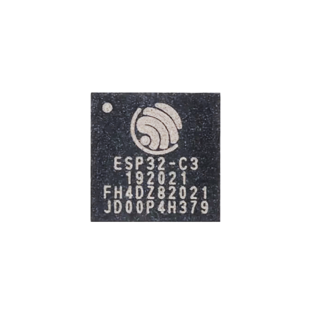
System-on-Chip (SoC)
The ESP32-C3 packs a single-core 32-bit RISC-V processor running at up to 160 MHz, and integrates Wi-Fi (802.11 b/g/n) and Bluetooth 5 (LE). It also offers hardware security features like secure boot and flash encryption, which make it ideal for secure IoT deployments.
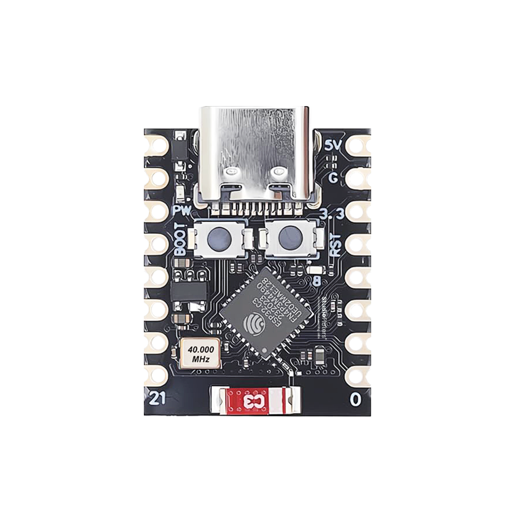
Development Board
The ESP32-C3 Super Mini development board includes a USB-C port for power and programming, two onboard buttons (EN and BOOT), and an onboard LED connected to GPIO8. It also provides access to all 21 GPIOs through castellated headers, making it ideal for both breadboarding and permanent installations.
Designed for Wireless + Low Power
Key features of the ESP32-C3 Super Mini:
- Microcontroller: ESP32-C3 FN4, 32-bit RISC-V single-core processor running at 160 MHz
- Connectivity: Supports 2.4 GHz Wi-Fi (802.11 b/g/n) and Bluetooth Low Energy (BLE) 5.0
- Memory: 4 MB flash storage
- Power: Can be powered via USB-C or through the 5V and GND pins
- Size: Extremely compact, ideal for space-limited projects
ESP32-C3 Super Mini Pinout Diagram

** The ESP32 C3 Super Mini pinout is available for download at the end of this post in high resolution – for free!
GPIO Overview
All GPIOs on the ESP32-C3 support multiple functions, but some pins come with specific capabilities or limitations.
General-Purpose GPIOs
All 21 GPIOs can operate as digital inputs or outputs and support interrupts. While most pins include internal pull-up or pull-down resistors, using external resistors is still recommended for improved stability.
Onboard LED
- GPIO8 – Controls the onboard blue LED.

Special Pin Functions
ADC (Analog-to-Digital Converter)
The ESP32-C3 has one ADC with up to 6 channels and 12-bit resolution.
- ADC Pins: GPIO0, GPIO1, GPIO2, GPIO3, GPIO4, GPIO5
- Applications: battery monitoring, potentiometers, temperature sensors
- Note: ADC performance is affected when Wi-Fi is active, especially under load.

PWM (Pulse Width Modulation)
All GPIOs except GPIO20 support PWM, ideal for:
- LED dimming
- Motor speed control
- Sound generation

I2C Communication
The ESP32-C3 supports multiple I2C buses, with pins freely assignable.
- Common configuration:
- SDA: GPIO5
- SCL: GPIO6
- Applications: OLED displays, sensors (BME280, MPU6050), EEPROMs.

SPI Communication
The hardware SPI interface can be mapped to multiple pins. Default (but configurable) mapping:
- MOSI: GPIO6
- MISO: GPIO5
- SCLK: GPIO4
- CS: GPIO7

UART Communication
The ESP32-C3 offers two UART interfaces. By default, it uses the following connection for serial debugging:
- TX: GPIO21
- RX: GPIO20
Used by the onboard USB-serial converter (CH340), no external hardware needed.

Strapping Pins
These are used during boot to configure the mode:
- GPIO8: Controls whether to enter bootloader mode (when BOOT is held)
- GPIO9: Connects internal flash (do not use!)
Important: Avoid using GPIO9 — it is connected to internal SPI flash.

USB Pins
The ESP32-C3 provides native USB support on GPIO18 and GPIO19, but most boards don’t use this feature. Instead, they typically rely on a CH340 USB-to-serial chip.
GPIO Reference Table
| GPIO | Special Function | ADC | PWM | Notes |
|---|---|---|---|---|
| 0 | ADC1_CH0 | Yes | Yes | I |
| 1 | ADC1_CH1 | Yes | Yes | |
| 2 | ADC1_CH2, SPI MISO | Yes | Yes | |
| 3 | ADC1_CH3 | Yes | Yes | |
| 4 | ADC1_CH4, SPI CLK | Yes | Yes | |
| 5 | ADC1_CH5, I2C SDA | Yes | Yes | |
| 6 | SPI MOSI | No | Yes | |
| 7 | SPI CS | No | Yes | |
| 8 | Onboard LED | No | Yes | Also strapping pin |
| 9 | SPI Flash (internal) | No | No | Do not use! |
| 10 | No | Yes | ||
| 20 | UART0 RX | No | No | |
| 21 | UART0 TX | No | No |
Best Practices & Warnings
Do:
- Use GPIO8 for onboard LED control
- Add debounce logic for buttons on GPIOs
- Pull-up SDA/SCL lines for I2C
Don’t:
- Use GPIO9 – it’s tied to the internal SPI flash
- Drive more than 12mA per pin
- Forget to consider boot strapping behavior
How to Program the ESP32-C3 Super Mini
Programming Methods
- Arduino IDE: Fast and beginner-friendly
- PlatformIO: Professional, powerful workflow
- ESP-IDF: Full control, official toolchain
Flashing the Board
The CH340 USB chip manages flashing over UART, eliminating the need for an external FTDI adapter.
Steps:
- Connect via USB-C
- Hold BOOT, press EN, then release BOOT
- Upload code
- Done! Most software (e.g. Arduino) does this automatically
Conclusion: Tiny Size, Massive Potential
The ESP32-C3 Super Mini shows that great things truly come in small packages. With its powerful RISC-V processor, reliable wireless connectivity, and built-in security features, this compact board is perfect for next-generation embedded applications. By understanding the pinout and leveraging its full potential, you can drive your projects into a new era of innovation.
Happy Building!
Download the ESP32-C3 Super Mini pinout here in high resolution – for free*!
* Free to use under the MIT license — attribution is required.